Specification of KN990 V4
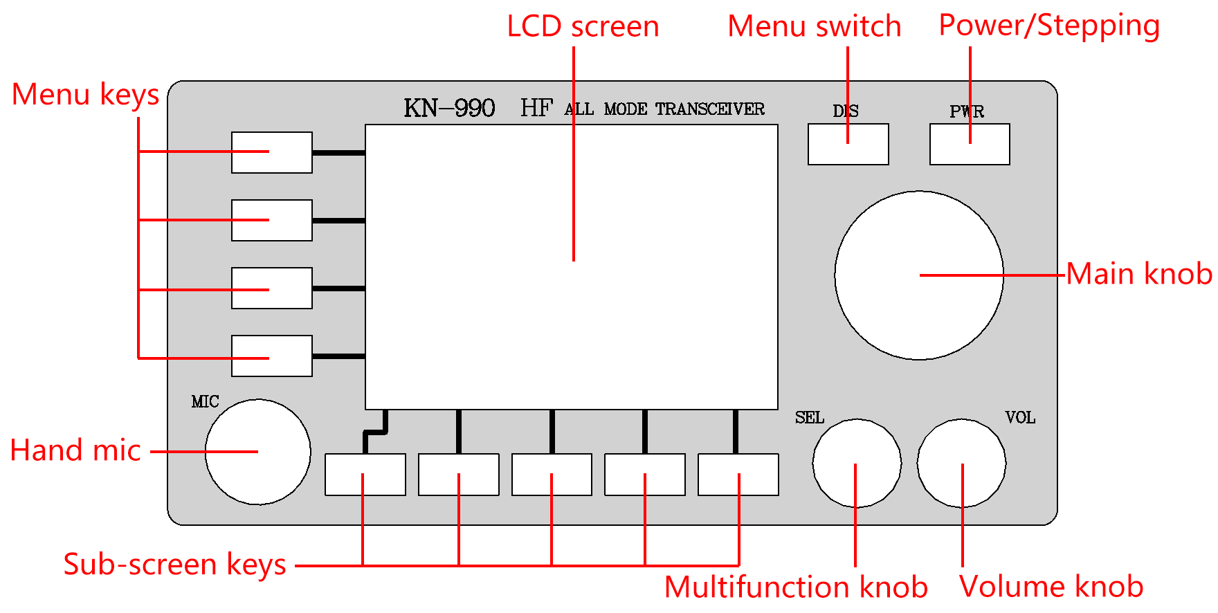
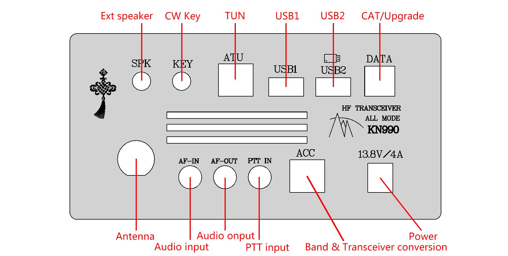
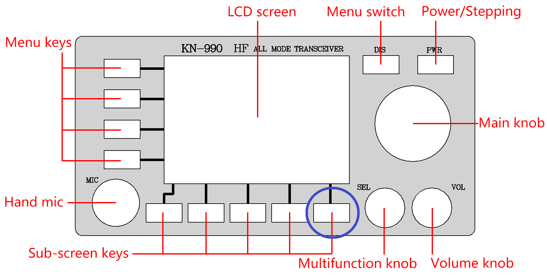
I. Introduction of front and rear panels
II. Switch the machine
1. Power on: Click the power button to turn on the machine.2. Power off: Press down the power button and hold it for about 1 second.
3. Note: All changes to the Settings of the radio station after starting up will only be saved when the power button is shut down with long press. If the power is cut off directly, the changes before power off will not be saved (the recording is an exception which is saved in real time).
III. Introduction of interface
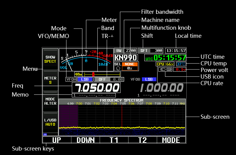
2. The lower part of the interface is called "sub-screen".
3. Five "sub-screen” buttons are displayed at the bottom of the sub-screen are corresponding to the five physical "sub-screen” buttons in the front panel.
IV. Working frequency (VFO)
1. Modify VFO: turn the main knob, VFO range: 0-150M.2. Modify stepping: click the power button and turn the main knob.
3. The modification of stepping can be directly switched between VFOA and VFOB.
4. By default, VFOA is both the receiving frequency and the transmitting frequency. When "Split" is enabled, VFOA is the receiving frequency and VFOB is the transmitting frequency.
V. Modulation mode
1. There are five modulation modes: SSB, CW, AM, FM and WFM.2. Switch modulation mode: click the menu "MODE ALTER".
3. Switch sideband: click the menu button "L/USB".
4. There are three types of sideband settings:
USB:force USB.
LSB band: LSB.
AUTO: LSB when VFO<10M, USB when VFO>=10M
VI. Menus
The menu has four buttons, the "SHOW" button is fixed, and using the DIS key can switch other three buttons.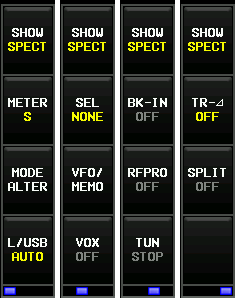
6.1.SHOW
Switch sub – screen circularly, sub - screen will be described in detail below.6.2.METER
There are two reception tables :" signal intensity "and" sound scale ".There are also two launch tables:" transmitted power "and" standing wave ratio".
Only launch when the launch table can be switched!
6.3.MODE
Switch SSB, CW, AM, FM, WFM five modulation modes circularly.SSB and CW will display USB, LSB, CW and CWR in different sideband.
6.4.L/USB
Switch "LSB","USB","AUTO".6.5.SEL
Specifies which parameters being set currently by the front panel "multifunction knob".Not used: multi-function knob never sets any parameters.
Transmitting power: 1~15W transmitting power.
Sending speed: the sending speed when the automatic key is in CW mode is 4-60wpm.
Bandwidth: receive bandwidth, different modulation modes have different bandwidth ranges, even the bandwidth is not adjustable.
Offset: receive offset, different modulation modes have different offset ranges, even the offset is not adjustable.
Increment: the increment will be described in detail below, the range: -9.99kHz~+9.99kHz.
VOX sensitivity: sensitivity of hands-free function (VOX): 1%~100%.
FM sensitivity: FM noise rejection sensitivity: 1%~100%.
WFM sensitivity: WFM noise rejection sensitivity: 1%~100%.
Waterfall brightness: di Ang independent adjustment of spectrum waterfall: 10~190.
6.6.VFO/MEMO
Switch VFO mode, storage mode and VFO mode circularly: there are two sets of working parameters (VFOA,VFOB), they include frequency, modulation mode, receiving bandwidth, and receiving offset, these parameters can be modified at any time, and they will be automatically saved when the machine is powered off.Storage mode: there are 99 sets of working parameters (MEMO1~MEMO99), they include frequency, modulation mode, receiving bandwidth, and receiving offset, which can be modified at any time, but they can only be saved by using the save button in the storage list interface.
Storage mode is the equivalent of a "favorites" function, which helps users record some favorite frequency points and its modulation mode.
Users can even set the name of the stored channel.
6.7.VOX
After being turned on, it will automatically enter the emission state according to the volume of sound input of audio. The sensitivity and emission delay of VOX can be adjusted (it will be described below).6.8.BK-IN
CW emission delay. The default state is off, which will turn off the CW emission delay after turn on it.6.9.RFPRO
Amplify the received signal 100 times.6.10.TUN
It needs to cooperate with KT series automatic TX tune.After clicking, it will start transmitting with the VFO,CW mode and 3W transmitting power and notify the automatic TX tune to start working.
When the automatic TX tune is completed, the launch will be closed automatically.
6.11.TR-△
TR-△ can be divided into receive and launch increments.The reception increment is similar to the "RIT" function of a traditional radio station.
The emission increment is similar to the function of "⊿TX " of a traditional radio station.
This function is mainly used when the frequency of opposite radio is found to be inaccurate.
Receive increment and transmit increment cannot be opened at the same time.
When the receiving increment is turned on, the actual receiving frequency =VFO+ increment value, and the transmitting frequency remains unchanged.
When the emission increment is turned on, the actual emission frequency =VFO+ increment value, and the receiving frequency remains unchanged.
Increment range: -9.99khz ~+ 9.99khz.
6.12.SPLIT
After opening, VFOA will be used as the receiving frequency and VFOB will be used as the transmitting frequency.The pilot frequency function can make the receiving and transmitting work in completely different frequency bands, and the increment is only within the offset range of ± 9.99k.
VII. Sub-screen
1. Switch the sub-screen: click the menu "SHOW".2. Each sub-screen has 5 corresponding sub-screen buttons, most of which are related to the current sub-screen.
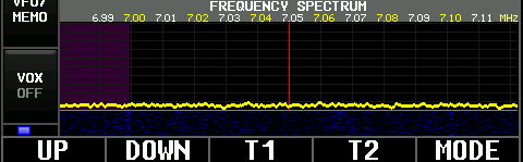
DOWN: it has the same function as the "up" key, and the switch direction is opposite.
T1: the recording content of T1 is transmitted in a circular manner.
T2: Emission T2 recording content circularly.
MODE: Switch big/small waterfall mode.
The center red bar indicates the current position of VFO.
The interval between two adjacent vertical lines is 10kHz.
The frequency (accurate to 10kHz) will be displayed above the vertical line, but it will not be displayed when the frequency >=100M.
The signal height will adapt to the screen height automatically to avoid strong signals spilling over the screen range, or signals are too weak to observe, so the height of the spectrum does not represent the absolute signal strength, but the relative signal strength of all signals in the current range of spectrum.
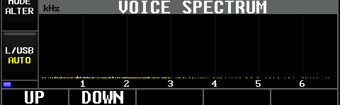
DOWN: it has the same function as the "up" key, and the switch direction is opposite.
The interval between adjacent vertical lines is 1kHz.
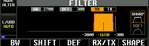
SHIFT: enter the mode of editing offset, the main knob adjusts the offset, and click again to exit this mode.
DEF: restore the current filter parameters to the default parameters.
RX/TX: Switch transmitting filter and receiving filter.
SHAPE: Switch the sharp displayed by band-pass graphics, which can be divided into sharp and soft.
The bandwidth and offset stepping are both 10Hz.
The filter parameters of all modulated modes are independent and do not affect each other.
The transmitting and receiving filters of all modulated modes are also independent and do not affect each other.
Different modulation modes will have different band-pass patterns.
The white vertical line represents the VFO position in the band-pass graph, and the black vertical line represents the band-pass center.
The white number below the band-pass figure represents the left and right boundary frequencies of the band-pass range, and the yellow number represents the band-pass center frequency.
Special note: the default emission offset in SSB mode is 300Hz. If the setting is too low, there will be carrier leakage during emission.
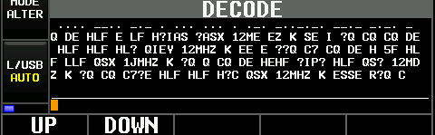
DOWN: it has the same function as the "up" key, and the switch direction is opposite.
Decoding function only supports CW decoding currently, which requires CW mode (sideband independent).
The information of dot drawing is displayed at the top of the interface, decoded characters are displayed in the middle, and characters input by USB keyboard are displayed at the bottom.
Decoding accuracy depends on stability of signal intensity and standard sending technique.
This interface can use USB keyboard to input characters and press enter key to send automatically.
When the last message is not sent out, press the back button to enter the waiting state, and the current message will be sent automatically after the last message is sent out.
DOWN: it has the same function as the "up" key, and the switch direction is opposite.
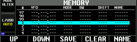
SAVE: store the current working frequency, modulation mode, receiving bandwidth, receiving offset into the currently selected channel.
CLEAR: clear the currently selected channel.
NAME: enter the mode of channel name editing, change the character with the big knob, move the cursor up and down, and click exit again.
Mode of channel name editing.
Menu "VFO/ storage mode "can be switched to storage mode, at this time the current channel information will be used as working parameters (including working frequency, modulation mode, receiving bandwidth, receiving offset).
Up to 99 channels can be saved.
Only when the sub-screen stays in the storage can it be switched to a blank channel. When the sub-screen is in the spectrum interface and is in storage mode currently, clicking the up and down keys will only switch in the non-blank channels.
MEMO+n will be displayed when channels are not named, otherwise the name set will be displayed.

T1:
Transmitting mode -> transmitting T1 recording content circularly (the speaker will not play the recording content during transmission);
Play mode -> local speaker plays T1 recording content in a loop, but it will not transmit;
Recording mode -> clear the old recording and ready to start the new recording. The recording will only be started when the PTT key of the microphone is pressed and the recording will be suspended when the PTT key is released.
T2: the same function as T1, but it operates T2 recording.
OPER: the loops among emission mode/play mode/recording mode.
INV: cycle interval between launch mode and play mode. In launch mode, only when recording is launched will the machine be in the launch state. In the interval time, the machine is in the receiving state and the sound will be demodulated normally.
TYPE: select whether the transmitting recording and playing synchronously or not.
Maximum support for T1 and T2 recording, each recording can record about 15.977 seconds.
The interface displays a graphical preview of the recording, and the height of the line indicates the sound.

UP/DOWN: move the cursor.
TX: launch the selected message content currently.
EDIT: edit the selected message content currently.
KEY: edit the selected message shortcut currently, the main knob and USB keyboard can be used to edit a single message witch up to 50 characters.
DOWN: moves the cursor down.
CLICK: to enter a selected project or start editing a value, most edits use the big knob to adjust the value and move the cursor up and down (if the cursor can be moved).
BACK: back up beyond level.
Explanations for all Settings are explained below.
VIII. CAT
KN990's CAT protocol is compatible with Yaesu FT817.In other words, any CAT software that supports FT817 can be used to operate KN990, such as "Ham Radio Deluxe".
Interface: square port USB on the back of the machine (usb-b type, printer USB port).
Baud rate: 38400.
IX. USB
KN990 currently supports three USB devices U disk, keyboard and gamepad.The back of the machine provides two USB ports that can work at the same time, but note that the USB disk can only work properly when plugged into the USB2, and other devices support both ports.
When the inserted USB device is properly recognized, the interface will display ICONS.
The following icon will be displayed when the inserted USB device is not properly recognized.
At present, the USB driver is not very stable, and sometimes it can be recognized or not. If plugging and unplugging repeatedly still doesn’t work, you can restart the machine and generally the problem will be solved.
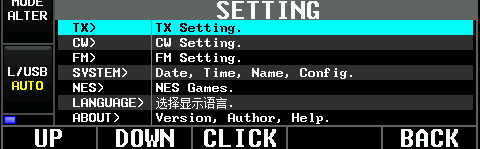
X. System setting
The system setting a multi-level menu. The name of each option which is followed by the symbol ">" is the entrance to the next level of menu, for example:
10.1.TX
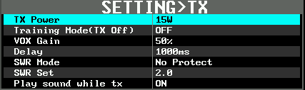
Training Mpde(TX Off): Nothing will be emitted under any circumstances except TUN after this option is turned on. This option is linked to Training Mpde in the CW setting (they are equivalent to the same option, which is shown in both menus).
VOX Gain: It will work when you turn on VOX. This option controls how much input volume you can trigger VOX.
Delay: this option controls how long should VOX and CW wait to close emission after the launch is finished at the same time. This option and Delay in CW setting are linked (they are equivalent to the same option, which is displayed in both menus).
SWR Mode: turn off Mode ->, turn off emission when standing wave is greater than or equal to threshold value, and turn off TUN and VOX simultaneously; when the standing-wave - threshold value is greater than 1, the actual transmitted power will decrease to 3W and no longer continue to decrease.
SWR Set: controls the value that triggers high standing wave protection.
Play sound while tx: The switch that when T1/T2 recording is transmitted automatically, the local speaker will alsoplay the recording content.
10.2.CW
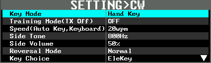
KN990 has the same auto key mode as FT817, Both of them belong to the press-one-key mode.
Training Mpde(TX Off): Nothing will be emitted except for TUN when this option is turned on. This option is associated with Training Mpde in the TX setting (equivalent to the same option was shown in both menus).
Speed: Speed of auto key and USB keyboard,4~60wpm, stepping 1wpm.
Side Tone: Control the local Side Tone at the time of transmission and the Side Tone at the time of reception simultaneously, 300~1200Hz, and stepping 50Hz.
Side Volume: Control the volume of local side at the time of transmission, 0%~100%.
Reversal Mode: Exchange the stipples of Auto Key.
Key Choice: The electronic key-> uses the Key socket on the back of the machine to send messages. Microphone key -> uses the plus and minus keys of the microphone to send messages.
Delay: this option controls how long should VOX and CW wait to close emission after the launch is finished at the same time. This option and Delay in TX setting are linked (equivalent to the same option, which is displayed in both menus).
10.3.FM

WFM sensitivity of Noise rejection: 1%~100%. Control when the signal intensity in WFM mode is lower than a certain value, the mute will start.
10.4.SYSTEM
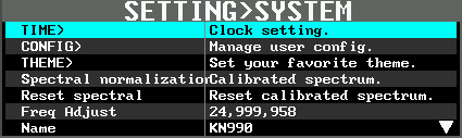
CONFIG:

Import from USB Disk: "config.rtf" file in the root directory of U Disk and apply all the configuration in it to the local machine. Please do not Import the configuration of other machines, because the configuration contains the pre-factory calibration parameters, each machine is different.
Default all config: restore all user configurations to the factory state, and the calibration parameters before delivery will not be restored.
Note: only usb sticks which support FAT or FAT32. If your usb stick is not in this format (such as NTFS), use Windows to format the usb stick into FAT32.
Usb flash drive can only be used normally at USB2 port on the back of the machine. If usb flash drive is inserted at USB1 port, it can be identified as usb flash drive, but files cannot be read or written.
THEME:
Spectrogram brightness: modify the overall brightness of spectrogram.
The remaining options are used to modify the color of display.
Press OK to open the color disk, use the main knob to select the color, press OK to save or Cancel to return, all color changes will take effect directly after the confirmation, dispense with restarting the machine.
Spectral normalization: affected by band-pass curve of the band-pass filter, the default spectrum noise may not be smooth, remove the antenna, adjust the working frequency to a clean frequency, and then use this option will normalized spectrum automatically to let the noise smooth.
Reset spectral: It can be used if the spectral normalized result is not ideal for some reasons.
10.5.NES

U Disk ROM: This option shows "U Disk ROM" when machine is leaving factory, after the U Disk loads games, this option will display the name of last loaded game, and the game can run out of the U Disk.
Load NES rom from the U Disk, set up folder "ROM" in the root directory of U Disk, Put game files which are NES format in ROM folder, insert U Disk into the USB2 behind machine, this option will be able to browse ROM folder and run the games in it. Keyboard: set up the game key mapping of USB Keyboard keys.
Joystick: Set the game key mapping of the USB gamepad.
Currently, only two built-in red and white machine games are supported. In the future, import games from usb flash drive freely will be supported.
Currently, only the keyboard can be used for Double game modes, and the gamepad only supports single player.
KN990 supports HID protocol gamepad with standard USB interface. If you are not sure which one you should choose, you can directly choose the WE-8400 model handle in the link below. There is also we-8600 model in the link. This is not supported, do not buy 8600, buy 8400!
https://detail.tmall.com/item.htm?id=39333429326&spm=a1z09.2.0.0.59cb2e8dqNTkGu&_u=735ehb1816b
10.6.LANGUAGE

10.7.About
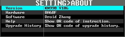
Hardware: BA6BF, author of Hardware.
Software: Droid Zhang, the author of Software.
Help: display the two-dimensional code of this instruction. After scanning it, you can see this instruction, the language of the instruction and the display language of the machine are consistent.
Upgrade History: display the two-dimensional code of the update log. You can see the updated contents of all versions by scanning the two-dimensional code.
XI. Firmware upgrade
Preparation:Get a Windows computer with Internet access.
2. Download the upgrade tool "KN990 upgrade tool".
Web page download http://www.zhiqiangtech.com/kn/kn990/KN990升级工具V2.exe
QQ group sharing download: group number 124321052.
3. Prepare a square port USB cable (USB-B, printer USB cable).
4. Prepare a usb flash drive.
Upgrade steps:
1. Enter SETTING-SYSTEM-CONFIG-Export to USB Disk.
Since upgrading firmware will forces a factory recovery one time, the configuration must be exported manually to avoid missing previous Settings.
2. Run the upgrade tool and wait for the latest version to be automatically obtained.
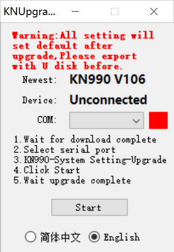
3. Use square USB cable to connect the radio to computer, and choose the serial port number.
If you can't find the serial port number of the radio station, you can check in the device manager of Windows whether it is because the CH340 driver is not installed. The driver has been uploaded by many users in the group file, so you can have a try.
If all goes well, the upgrade tool will display a green square.
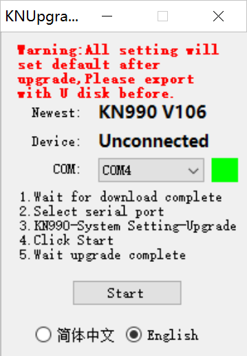
4. Enter SETTING-SYSTEM-UPGRADE
At this point, the upgrade tool interface can get the local version number of your radio.
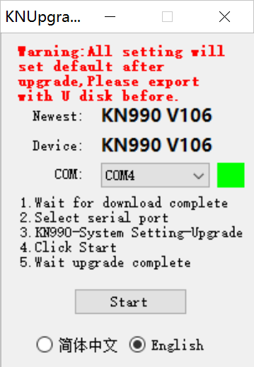
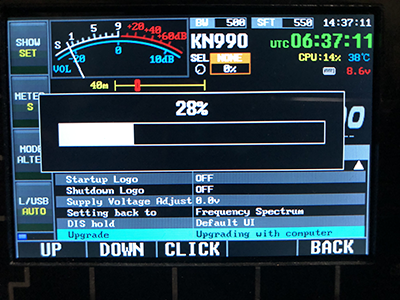
5. Click the "Start" button of the upgrade tool. After a moment, the upgrade tool and the progress bar of the radio start to move.

6. After the upgrade is completed, the station will automatically restart and forcibly restore the factory settings, enter setting-systems-config-import from U Disk, and the upgrade is completed
Upgrade failed:
If the upgrade process is interrupted due to power failure, poor USB contact, computer crash and other unexpected circumstances, then the radio station will not be able to start up normally (become a brick), and the upgrade cannot be resumed according to the above steps, please follow the following steps to save the machine.
1. Cut off the power of the radio station and force it to shut down.
2. Close the upgrade tool than reopen it.
3. Plug in the radio power supply and use the square USB cable to connect the radio to computer.
4. Hold down the last key on the right side of the sub-screen button at the bottom of the front panel of the radio station (shown in the figure below, as shown in the blue circle), at the same time click the power button quickly (note that it is a quick click, do not hold down or hold for too long).
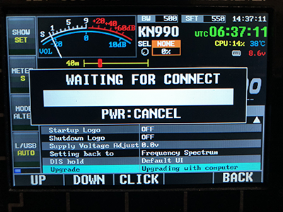
At this point, the radio will be forced into a bootstrap program, and the interface is shown as follows:
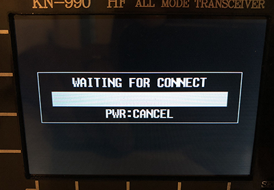
6. If the serial port number is selected, the firmware version of the radio station is read and the green square is displayed, which indicate that the connection is successful, then click “Start”. If the firmware of the radio station is not read normally, please go back to step 1 and Start again.
7. Wait patiently for the progress bar to finish after upgrading.
Note: no matter what happens in the normal upgrade process, you can use the above steps to save the plane. It would never become bricks. So please release the upgrade. Don't worry about it.
XII. Screenshots
KN990 provides interface screenshots.1. Insert the U disk into the USB2 port on the back of the machine.
2. Insert the USB keyboard into the USB1 port on the back of the machine.
3. Press the PrtSc key on the keyboard (this key is usually on the right of F12).
4. The screenshot needs a few seconds, during which the radio interface will pause to refresh. After the screenshot is completed, the interface will resume to refresh and prompt "complete".
The screenshot file will be saved in the root directory of U disk "kn990. BMP".
Note: the currently captured images are upside down. You can use the drawing tool (Ctrl+A) in windows to select all of them and flip them vertically. There will be color difference between the screenshot color and the actual display color of the radio.
XIII. Limitation of VFO scope
The default VFO range of KN990 is 0~150M. For some special requirements. Providing a hidden switch can limit the VFO range to 3~30M.1. Adjust VFO frequency to 12.345.67.
2. Press and hold the power button to shut down.
3. Press the power button to start up.
4. At this time, the VFO range has become 3~30M.
If you want to revert to the previous VFO range, repeat the steps above.